Dynomotion

Group: DynoMotion Message: 9439 From: Hugh Sontag Date: 5/1/2014
Subject: SnapAmp faulting still occuring
Hi Tom,

I finally got our CNC router back together, and I'm still seeing the same behavior I reported earlier.

I have learned a bit more about when this happens.

Our CNC router has 4 stepper motors, 7A max per coil. Two motors are connected to SnapAmp0 (I call them X0 and X1), and those control X movement of the gantry.

Two more motors are connected to SnapAmp1, one each for the Y and Z axis.

I find that if all four motors are connected to the SnapAmps, I get faulting. The interesting part is that if only two motors are connected (two to SnapAmp0 or two to SnapAmp1), then those two motors work without a problem.

Here is a detailed description of the tests I did today:

All of these tests were done with the X motors disengaged from the rack and pinion, so that the gantry didn't move in X, and there was virtually no mechanical load on the X motors. The Y and Z motors were fully engaged, so that as the motors moved, so did the Y and Z mechanisms.

1. I connected the X0 and X1 motors to SnapAmp0 (Y and Z axis motors not connected) and ran the motors successfully. In the end, I put together a small C program that moves the axis back and forth continuously.

2. Then I connected the Y and Z motors to SnapAmp1, leaving the X motors connected to SnapAmp0. After powering up, I ran the initialization program, then enabled *only* axis 0 and 1 (X0 and X1 motors, respectively).

I got faulting as soon as I enabled the motors.

3. I then took the plug for the X0 and X1 motors and connected it to SnapAmp1, instead of SnapAmp0. Y and Z motors were disconnected. I was able to exercise the X0 and X1 motors without a problem using commands for the Y and Z axes 2 and 3.

4. I connected all four motors again to their normal positions (X0 and X1 on SnapAmp0, Y and Z motors on SnapAmp1. This time I enabled the Y and Z axes and got faulting again.

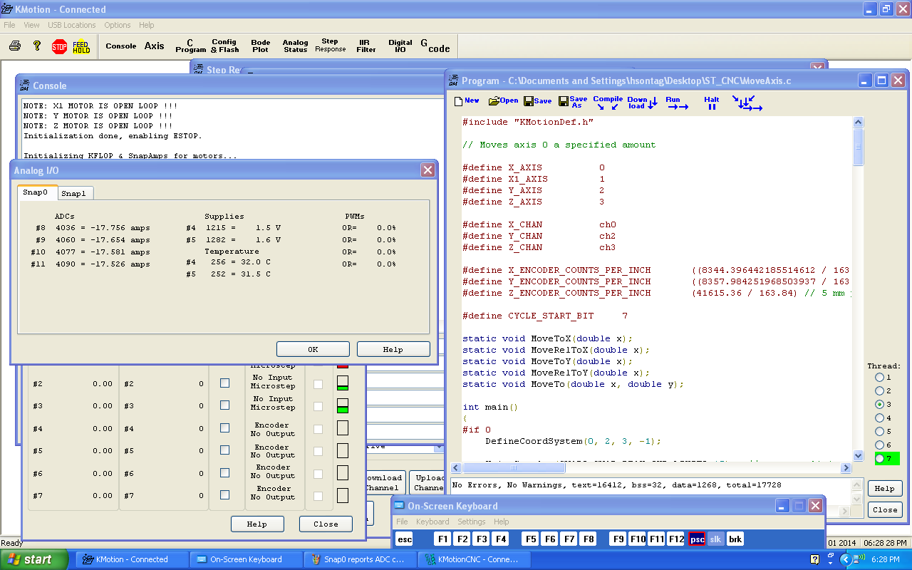
But there's something interesting. The "Analog Status" window showed that SnapAmp0 was exceeding the max current, *** even though the axes on SnapAmp0 were never enabled ***. The current for both axes on SnapAmp1 were within the normal range (less than 7 A for each coil).

I've attached a screen shot of the SnapAmp0 overcurrent, which occurred, as I mentioned, even though the SnapAmp0 axes were never enabled. 

-> As an aside, can you tell me why the SnapAmp currents seem to stick at very high levels (but still change somewhat, so the numbers vary but stay very high) after a fault occurs? This occurs even after disabling the axes for that SnapAmp, and even after turning off the power supply, so that there *can't* be any current flowing in the motors.

Prologue - I also measured resistances, again, for the X1 motor coil leads, as I rotated the motor, just to be sure there wasn't an intermittent short internal to the motor. I measured resistance from coil to coil, and also from coil to the motor case. I didn't find any short, although I did measure the expected coil resistance of approx. 0.5 ohm across the coil.

It appears to me that the motors are good (they work fine two at a time), and the wiring, along with being visually inspected and nothing found amiss, electrically measures good. All four motors work properly when run in pairs.

How can we get our CNC router working properly?

Thanks,
Hugh


  @@attachment@@
Group: DynoMotion Message: 9441 From: Tom Kerekes Date: 5/2/2014
Subject: Re: SnapAmp faulting still occuring [1 Attachment]
Hi Hugh,

Weird.  Sorry you are still having problems.  Thanks for the very detailed problem description.  We are looking into it and have a few questions.

SnapAmp has an automatic current offset calibration mechanism.  This is to correct for small offsets in the current measurement circuitry.  I suspect the problem has something to do with this.  As soon as KFLOP boots up and configures SnapAmp the first thing SnapAmp does is make a current measurement on all 4 current measurement channels.  The assumption is that all FETs are off and there is no current flowing so the current should be zero.   It then records the measured current to be used as an offset in all subsequent current measurements.  There is also a method to trigger a re-calibration by reading a special "Reset" register in the the FPGA.  We don't intentionally ever do a SnapAmp Reset and to be honest I'm not sure how well it works.  It definitely would be a problem if this reset was performed while current was flowing.

My best guess at this point is that we have a software bug in our code or your code that is performing a reset at the wrong time.  Another possibility is some communication noise issue causing an unexpected reset. 

I'd like to focus on your Step #2 which I understand to be a simple sequence to repeatedly cause a problem.

Question on the history of this problem.  Am I correct that this all worked fine at one time and you were able to run those large GCode files and so forth and then somehow this problem popped up?

What Version are you running?  Please send your Initialization program that you are using in your Step #2.

How many motor power supplies do you have?

In Step #2 is the power supply for SnapAmp #1 (Y+Z) connected?  Powered up?

So if I understand everything correctly, the only difference between sequence #1 that works driving X0 and X1, and sequence #2 that fails driving X0 and X1, is that the Y and Z motors are electrically connected (and maybe the motor power supply is also connected to SnapAmp #1)?

Regards
TK


Group: DynoMotion Message: 9443 From: Hugh Sontag Date: 5/2/2014
Subject: Re: SnapAmp faulting still occuring
Hi Tom,

Here are answers to your questions:

> Question on the history of this problem.  Am I correct that this all worked fine at one time and you were able to run those large GCode files and so forth and then somehow this problem popped up?

Yes, you are correct. We ran quite a lot of GCode, actually cutting parts, before this problem occurred.

> What Version are you running?  Please send your Initialization program that you are using in your Step #2.

The version is KMotion/KFLOP Version 4.31s, as reported from the "About KMotion" window. I've attached the initialization program "InitHughsCNC.c".

> How many motor power supplies do you have?

There is one power supply. It is capable of sourcing 22A. The output voltage was 72V. I did also try Step #2 with a voltage of 65V, with no difference in results (immediate faulting after enabling axis 0 and 1).

In Step #2 is the power supply for SnapAmp #1 (Y+Z) connected?  Powered up?

Yes, in Step #2 the power supply for SnapAmp1 is connected and powered up. It's the same power supply that provides power to SnapAmp0.

The one power supply provides power to both SnapAmps, through the detachable connector at the edge of the SnapAmp boards. Two pairs of wires go from the power supply DC output terminals to the SnapAmp JP1 connectors. One pair of wires go to SnapAmp0 (with a Y just before connecting to JP1), and another pair of wires go to SnapAmp1.

The 220VAC power to the power supplies is on a separate switch to the switch that turns the KFLOP power on and off. I have often run "InitHughsCNC.c" prior to turning on the power supply to the SnapAmps. Perhaps you can tell me whether this is a good idea or not; I have assumed that the SnapAmp power control section is isolated from the logic.

Today, I ran Step #2 and took care to turn on the motor power supply prior to running "InitHughsCNC.c". I still get immediate faulting after enabling axes 0 and 1. I don't have to try to move a motor - the faulting occurs without moving a motor.

> So if I understand everything correctly, the only difference between sequence #1 that works driving X0 and X1, and sequence #2 that fails driving X0 and X1, is that the Y and Z motors are electrically connected (and maybe the motor power supply is also connected to SnapAmp #1)?

Yes, you are correct. Since the motor power supply to SnapAmp #1 is wired to the detachable connector JP1 on the SnapAmp, it is connected to the SnapAmp when the motors are connected to the SnapAmp. Similarly, it is disconnected from SnapAmp1 when the motors are disconnected from the SnapAmp.

---

Regarding grounding, the KFLOP and Snap Amps have a single +5V supply whose ground is connected to the third prong ground of the AC input. The motor power supply has no ground other than the ground provided by the SnapAmps. I measured the resistance from the SnapAmp negative power supply input to the KFLOP ground as zero ohms, so I assume that the motor power supply has a single ground through the SnapAmps.

Because we were not satisfied with the performance of our encoders due to some noise which was coupling even into our differential encoder lines, I built PC boards which optically isolate the encoders from the KFLOP. This means that there is *no* electrical connection to the KFLOP and SnapAmps other than the following:

- Optical isolator output logic, all of which is located with 2 inches of the SnapAmp 50-pin connectors. The output sections of the opto isolators are powered from the SnapAmp +5V on the 5-pin connector;

- +5V power supply;

- Stepper motor wiring, which is connected to the SnapAmp JP1 connectors. Shields for the stepper motor wires are connected separately to a single-point ground.

The encoders and drivers for the LEDs in the opto-isolators are now powered by a separate, isolated 9-volt supply that has no connection to the KFLOP ground. I can report that the optically isolated encoder position data looks very clean, and looks better than I ever saw it running with differential drivers.

That said, this problem also occurred before optically isolating the encoders. It's another indication, in my opinion, along with the results after adding the optical isolators, that grounding would not appear to be the root cause of the problem.

Hugh


On Fri, May 2, 2014 at 2:18 PM, Tom Kerekes <tk@...> wrote:
 

Hi Hugh,

Weird.  Sorry you are still having problems.  Thanks for the very detailed problem description.  We are looking into it and have a few questions.

SnapAmp has an automatic current offset calibration mechanism.  This is to correct for small offsets in the current measurement circuitry.  I suspect the problem has something to do with this.  As soon as KFLOP boots up and configures SnapAmp the first thing SnapAmp does is make a current measurement on all 4 current measurement channels.  The assumption is that all FETs are off and there is no current flowing so the current should be zero.   It then records the measured current to be used as an offset in all subsequent current measurements.  There is also a method to trigger a re-calibration by reading a special "Reset" register in the the FPGA.  We don't intentionally ever do a SnapAmp Reset and to be honest I'm not sure how well it works.  It definitely would be a problem if this reset was performed while current was flowing.

My best guess at this point is that we have a software bug in our code or your code that is performing a reset at the wrong time.  Another possibility is some communication noise issue causing an unexpected reset. 

I'd like to focus on your Step #2 which I understand to be a simple sequence to repeatedly cause a problem.

Question on the history of this problem.  Am I correct that this all worked fine at one time and you were able to run those large GCode files and so forth and then somehow this problem popped up?

What Version are you running?  Please send your Initialization program that you are using in your Step #2.

How many motor power supplies do you have?

In Step #2 is the power supply for SnapAmp #1 (Y+Z) connected?  Powered up?

So if I understand everything correctly, the only difference between sequence #1 that works driving X0 and X1, and sequence #2 that fails driving X0 and X1, is that the Y and Z motors are electrically connected (and maybe the motor power supply is also connected to SnapAmp #1)?

Regards
TK


Group: DynoMotion Message: 9445 From: carlcnc Date: 5/2/2014
Subject: Re: SnapAmp faulting still occuring
Hugh
 If I may jump in here

   I ALWAYS take the neg  DC from my power supply and the incoming AC to a star ground
    this may solve your problem
Carl
   
Group: DynoMotion Message: 9446 From: Tom Kerekes Date: 5/3/2014
Subject: Re: SnapAmp faulting still occuring [1 Attachment]
Hi Hugh,

Thanks for all the answers.  But to be honest I still have no idea what is going on.

I don't see any problem in the Init C program.  But I would remove all that limit and Estop Testing temporarily just to eliminate that as a possibility.

You said:
>>Regarding grounding, the KFLOP and Snap Amps have a single +5V supply whose ground is connected to the third prong ground of the AC input.

I think this might be a bad idea and might form a ground loop and/or be coupling earth ground noise directly into KFLOP GND.  Please try removing it.

In your last several emails you didn't describe ever trying to run Y and Z by themselves.  But I think in a much earlier email you mentioned that Y and Z work by themselves.  I will assume this is the case.

I know you checked your wiring several times, but I don't recall you ever checking for shorts between coils or to shields.   I know it would unlikely or almost impossible but if it were me I would check for this as it should only take a few minutes.  There are 8 motor coils and an earth ground.  Total of 9 things that should all be completely isolated.  Please check all combinations are open.  (8+7+6+5+4+3+2+1) measurements.

So restating the Step#2 problem:  SnapAmp#0 faults driving X0 X1 when SnapAmp#1 has motors and Motor Power Connected

To try to get more clues please try the following:

(try partially connecting SnapAmp#1 to see exactly what is causing the problem)
#1 Connect only Motor DC GND to SnapAmp #1 - does X0 X1 still work ok?

#2 Connect Only Motor Power (+72V and GND) to SnapAmp #1 - does X0 X1 still work ok?

#3 Connect only Y and Z motor Coils (no Motor Power) to SnapAmp #1 - does X0 X1 still work ok?

(try swapping SnapAmps to see if the problem follows a specific SnapAmp)
#4 Swap Motor Connectors and I0 connectors, move jumper to opposite SnapAmp - do you get exactly the same behavior as before?

Sorry for no simple answer.
Regards
TK


Group: DynoMotion Message: 9448 From: Hugh Sontag Date: 5/3/2014
Subject: Re: SnapAmp faulting still occuring
Hi Tom,

Thanks for your thoughts on the problem.

> I don't see any problem in the Init C program.  But I would remove all that limit and Estop Testing temporarily just to eliminate that as a possibility.

I have removed the calls that check the limits and ESTOP. However, I have to point out that a) this code has been working correctly for quite a while prior to the occurrence of the problem, and b) even if the code weren't correct, its only effect would be to disable the axes, not initiate a fault.

You said:
>>Regarding grounding, the KFLOP and Snap Amps have a single +5V supply whose ground is connected to the third prong ground of the AC input. 

> I think this might be a bad idea and might form a ground loop and/or be coupling earth ground noise directly into KFLOP GND.  Please try removing it. 

You may not be aware that we use a laptop to control the KFLOP. The laptop has an isolated power supply and no direct connection to earth ground. I checked with an ohmmeter, with the laptop connected and powered on, and the only earth ground connection for the KFLOP is via the +5V power supply. There is no earth ground connection via the USB cable between the KFLOP and the laptop.

> In your last several emails you didn't describe ever trying to run Y and Z by themselves.  But I think in a much earlier email you mentioned that Y and Z work by themselves.  I will assume this is the case.

I have run the Y and Z axes successfully by themselves, with no motors or power connected to SnapAmp0, on multiple occasions. However, if the X0 and X1 motors are connected to SnapAmp0, I get faulting when I try to run the Y and Z axes.

> I know you checked your wiring several times, but I don't recall you ever checking for shorts between coils or to shields.   I know it would unlikely or almost impossible but if it were me I would check for this as it should only take a few minutes.  There are 8 motor coils and an earth ground.  Total of 9 things that should all be completely isolated.  Please check all combinations are open.  (8+7+6+5+4+3+2+1) measurements.

I checked every combination and found that there are no shorts, or even an impedance less than 10 Mohms, between any of the coils and the system star earth ground (which all the shields are connected to), or any of the coils and the other coils.

> So restating the Step#2 problem:  SnapAmp#0 faults driving X0 X1 when SnapAmp#1 has motors and Motor Power Connected

That's correct.

> To try to get more clues please try the following:

For a baseline, I connected X0 and X1 motors (and power) only to SnapAmp0. The +5V power supply AC earth ground is disconnected. These axes still work OK.

> (try partially connecting SnapAmp#1 to see exactly what is causing the problem)
> #1 Connect only Motor DC GND to SnapAmp #1 - does X0 X1 still work ok?

Connected only the +72V power supply GND to SnapAmp1. The X0 and X1 motors still work OK.

> #2 Connect Only Motor Power (+72V and GND) to SnapAmp #1 - does X0 X1 still work ok?

Connected only +72V Motor Power and +72V Motor GND to SnapAmp1. The X0 and X1 motors still work OK.

> #3 Connect only Y and Z motor Coils (no Motor Power) to SnapAmp #1 - does X0 X1 still work ok?

Connected only Y and Z motor coils to SnapAmp1. Faulting occurs when axes 0 and 1 are enabled.

I tried disabling both axis 0 (motor X0) and axis 1 (motor X1). The fault sound (clack clack clack) went away.

Then I enabled just axis 1. It made a normal sound for about a second, then the sound went away, and there was no sound at all. No fault noise, either. With axis 1 disabled, I enabled axis 0. No sound occurred then either.

When I looked at the Analog Status, the SnapAmp0 current for ADCs #8 and #9 are -34 amps. The current for ADCs #10 and #11 are 0.8 amps. The numbers are not static, they change slightly with time.

The Analog Status for Snap1 show ADC currents all less than 0.2 amps.

Even with the Motor Power supply turned off (0 Volts), the #8 and #9 ADCs still show -34 amps.

Now I'll turn off the power to the KFLOP + SnapAmps to clear the apparently locked current measurement on SnapAmp0.

---

Connected only the Y motor coils to SnapAmp1, no motor power supply connection. When axis 0 (motor X0) and axis 1 (motor X1) are enabled, the normal sound is made. So far so good. However, immediately after starting to run the motors, the X0 motor made a very coarse, loud sound, and then faulting started.

This time, Analog Status for SnapAmp0 ADCs #8, #9, #10 and #11 are all -20 to -21 amps.

SnapAmp1 ADCs #12 through #15 are all less than 0.25 amps.

---

Connected only the Z motor coils to SnapAmp1, no motor power supply connection. When axis 0 (motor X0) and axis 1 (motor X1) are enabled, again, the normal sound is made. Immediately after starting to run the motors, faulting started. There was no coarse noise from the X0 motor this time.

This time, Analog Status for SnapAmp0 ADCs #8 & #9 are -30A, #10 and #11 are -21 amps, even with all axes disabled. The numbers on SnapAmp0 ADCs stay at the same values even after turning off the motor power supply.

---

> (try swapping SnapAmps to see if the problem follows a specific SnapAmp)
> #4 Swap Motor Connectors and I0 connectors, move jumper to opposite SnapAmp - do you get exactly the same behavior as before?

Swapped the Motor Connectors (Z motor windings are the only connection to one connector), swapped the jumper identifying SnapAmp1.

Enabled X0 and X1 motors (axis 0 and 1), normal motor sound. Then tried running the motors. This time, they ran for about 6 seconds and faulting started. The box for current next to axis 3 intermittently showed red.

SnapAmp1 ADCs #12 through #15 are all less than 0.11 amps, SnapAmp0 ADCs #8 and #9 are at -4.8 A and -4.5A respectively, ADCs #10 and #11 are -9.2 A and -9.4 A.

Trying to enable axis 0 at this point causes the coarse loud sound from the X0 motor again. Enabling axis 1 seems to work OK - normal quiescent noise from the X1 motor. I didn't try to run the X1 motor, as it is slaved to the X0 motor.

---

Disconnected the Z axis Motor connector. SnapAmps are still swapped. Running the X0 and X1 motors back and forth worked fine.

--- 

Connected the Y axis motor where the Z axis motor was connected (OUT4 and OUT5, OUT6 and OUT7). Enabling axis 0 and 1 works doesn't cause a fault. Running the motors works for about 6 seconds, then the motors stop turning. Although the "PWMs" for Snap0 show changing values as if the motors are still being exercised, the motors don't move at all.

--- 

Swapped the Motor Connectors back, changed the jumper for SnapAmp1 back. The Y axis motor is still the only connection on its Motor Connector, but it's still connected in the Z axis position (OUT4 and OUT5, OUT6 and OUT7).

Enabled axis 0 and axis 1, normal motor sound. Tried to run the motors, faulting occurred within 5 seconds. Disabling axes 0 and 1 stops the faulting, and re-enabling them results in a normal motor sound. Attempting again to run the motors back and forth results in faulting.

---

All the above tests were performed with no AC earth ground connected to the +5V supply for the KFLOP. The last half of the tests were performed with the limit and ESTOP tests disabled, which (as expected) made no difference in the results.

Because the KFLOP and Snap Amps are tightly coupled, it's difficult to identify a single culprit. Any hypothesis as to the nature of the problem has to account for the fact that the system was working correctly and then started not working, the problem doesn't appear to follow a single SnapAmp, and that the problem manifests with only motor windings attached to the second SnapAmp.

It could be a single SnapAmp that's misbehaving, or the problem could be in the KFLOP's communication with the SnapAmps. The only sure thing is that it's one of the three.

My favorite theory is that some of the FETs that drive the motor windings are getting turned on when they shouldn't be, maybe due to a KFLOP / SnapAmp communications failure, which causes an overcurrent when the current builds in the motor winding past the current limit, which causes faulting.

The only next step that makes sense to me is to either swap all three boards out, or swap them one at a time, to identify which board the problem follows.

What's your take, Tom?

Hugh


On Sat, May 3, 2014 at 12:30 PM, Tom Kerekes <tk@...> wrote:
 

Hi Hugh,

Thanks for all the answers.  But to be honest I still have no idea what is going on.

I don't see any problem in the Init C program.  But I would remove all that limit and Estop Testing temporarily just to eliminate that as a possibility.

You said:
>>Regarding grounding, the KFLOP and Snap Amps have a single +5V supply whose ground is connected to the third prong ground of the AC input.

I think this might be a bad idea and might form a ground loop and/or be coupling earth ground noise directly into KFLOP GND.  Please try removing it.

In your last several emails you didn't describe ever trying to run Y and Z by themselves.  But I think in a much earlier email you mentioned that Y and Z work by themselves.  I will assume this is the case.

I know you checked your wiring several times, but I don't recall you ever checking for shorts between coils or to shields.   I know it would unlikely or almost impossible but if it were me I would check for this as it should only take a few minutes.  There are 8 motor coils and an earth ground.  Total of 9 things that should all be completely isolated.  Please check all combinations are open.  (8+7+6+5+4+3+2+1) measurements.

So restating the Step#2 problem:  SnapAmp#0 faults driving X0 X1 when SnapAmp#1 has motors and Motor Power Connected

To try to get more clues please try the following:

(try partially connecting SnapAmp#1 to see exactly what is causing the problem)
#1 Connect only Motor DC GND to SnapAmp #1 - does X0 X1 still work ok?

#2 Connect Only Motor Power (+72V and GND) to SnapAmp #1 - does X0 X1 still work ok?

#3 Connect only Y and Z motor Coils (no Motor Power) to SnapAmp #1 - does X0 X1 still work ok?

(try swapping SnapAmps to see if the problem follows a specific SnapAmp)
#4 Swap Motor Connectors and I0 connectors, move jumper to opposite SnapAmp - do you get exactly the same behavior as before?

Sorry for no simple answer.
Regards
TK


Group: DynoMotion Message: 9451 From: Tom Kerekes Date: 5/4/2014
Subject: Re: SnapAmp faulting still occuring
Hi Hugh,

Once again thanks again for all the detailed tests and description.

So just connecting the motor coils up to SnapAmp#1 with no motor power on SnapAmp#1 somehow appears to cause communication errors between KFLOP and SnapAmp#0.

I agree possibly something happened to one or more of the 3 boards to make the communication marginal.

Dynomotion will send a set of 3 new boards for you to swap out as a test.   Is the same address as before still correct?  

Regards
TK


Group: DynoMotion Message: 9456 From: Hugh Sontag Date: 5/4/2014
Subject: Re: SnapAmp faulting still occuring
Thanks, Tom. Yes, the same 2501 address is still correct.

Hugh


On Sun, May 4, 2014 at 12:24 PM, Tom Kerekes <tk@...> wrote:
 

Hi Hugh,

Once again thanks again for all the detailed tests and description.

So just connecting the motor coils up to SnapAmp#1 with no motor power on SnapAmp#1 somehow appears to cause communication errors between KFLOP and SnapAmp#0.

I agree possibly something happened to one or more of the 3 boards to make the communication marginal.

Dynomotion will send a set of 3 new boards for you to swap out as a test.   Is the same address as before still correct?  

Regards
TK


Group: DynoMotion Message: 9464 From: studleylee Date: 5/8/2014
Subject: Re: SnapAmp faulting still occuring
Is there any way you guys can delete the message history when you reply, or just quote the last context.
I get digests and they are nearly unreadable with the thread for each message getting longer and longer.
Cant tell where the respondent has added new information.
Thanks, -Lee

Idea: Hugh you mentioned making encoder isolation circuits. If your motors are running closed loop w/ encoder feedback, getting one signal backwards on an axis will cause a positive feedback situation short-term fast runaway and maybe the faults you are seeing are a response to that. Does the issue stay on a single axis's configuration? Just an idea thrown out there.
Group: DynoMotion Message: 9465 From: studleylee Date: 5/8/2014
Subject: Re: SnapAmp faulting still occuring
Slow encoder optos could give an alias-like issue to make the controller think the direction is reversed.
Use GMR or optos with an internal digital buffer( will need a small isolated 5V supply for the outboard side)
-Lee
Group: DynoMotion Message: 9466 From: studleylee Date: 5/8/2014
Subject: Re: SnapAmp faulting still occuring
What optos are you using? They would have to be fast ones with the internal digital buffer to be fast enough for an encoder. I use either the Avago optos or magnetic: GMR types from NVE, TI, or analog devices.

If you optos are of the normal NPN type, you might have some weird aliasing due to the slow speeds and the signals will look to the controller like its going the wrong way.


Because we were not satisfied with the performance of our encoders due to some noise which was coupling even into our differential encoder lines, I built PC boards which optically isolate the encoders from the KFLOP. This means that there is *no* electrical connection to the KFLOP and SnapAmps other than the following: - Optical isolator output logic, all of which is located with 2 inches of the SnapAmp 50-pin connectors. The output sections of the opto isolators are powered from the SnapAmp +5V on the 5-pin connector;


---In DynoMotion@yahoogroups.com, <indigo_red@...> wrote :


Group: DynoMotion Message: 9471 From: Hugh Sontag Date: 5/9/2014
Subject: Re: SnapAmp faulting still occuring
I agree that getting an encoder feedback signal backwards would cause runaway. However, that isn't the situation here. I've successfully run one axis with encoder feedback without runaway, so the encoder feedback can't be backwards.

Also, all the testing I've been reporting is without encoder feedback. The motors are running open-loop, to reduce the complexity of the problem. However, the problem occurs running open loop.

Hugh

On Thu, May 8, 2014 at 10:15 PM, <indigo_red@...> wrote:

Idea: Hugh you mentioned making encoder isolation circuits. If your motors are running closed loop w/ encoder feedback, getting one signal backwards on an axis will cause a positive feedback situation short-term fast runaway and maybe the faults you are seeing are a response to that. Does the issue stay on a single axis's configuration? Just an idea thrown out there.


Group: DynoMotion Message: 9472 From: Hugh Sontag Date: 5/9/2014
Subject: Re: SnapAmp faulting still occuring
The optoisolators aren't slow. I've tested the speed to 400 KHz and found less than 2 uSec of delay through the optos.

Hugh

On Thu, May 8, 2014 at 10:42 PM, <indigo_red@...> wrote:
 

Slow encoder optos could give an alias-like issue to make the controller think the direction is reversed.
Use GMR or optos with an internal digital buffer( will need a small isolated 5V supply for the outboard side)
-Lee